--INSERT RECORDS INTO EVENTPLANLINE
Insert into EVENTPLANLINE (PLANNO,LINENO,TIMESTART,TIMEEND,NUMBERFLD,LOCNO,RESNO) values ('P100',1, to_date('25-OCT-13 8:00:00','DD-MON-RR HH24:MI:SS'), to_date('25-OCT-13 17:00:00','DD-MON-RR HH24:MI:SS'),2,'L100','R100');
Insert into EVENTPLANLINE (PLANNO,LINENO,TIMESTART,TIMEEND,NUMBERFLD,LOCNO,RESNO) values ('P100',2, to_date('25-OCT-13 12:00:00','DD-MON-RR HH24:MI:SS'),to_date('25-OCT-13 17:00:00','DD-MON-RR HH24:MI:SS'), 2,'L101','R101');
Insert into EVENTPLANLINE (PLANNO,LINENO,TIMESTART,TIMEEND,NUMBERFLD,LOCNO,RESNO) values ('P100',3, to_date('25-OCT-13 7:00:00','DD-MON-RR HH24:MI:SS'), to_date('25-OCT-13 16:30:00','DD-MON-RR HH24:MI:SS'), 1,'L102','R102');
Insert into EVENTPLANLINE (PLANNO,LINENO,TIMESTART,TIMEEND,NUMBERFLD,LOCNO,RESNO) values ('P100',4, to_date('25-OCT-13 18:00:00','DD-MON-RR HH24:MI:SS'),to_date('25-OCT-13 22:00:00','DD-MON-RR HH24:MI:SS'),2,'L100','R102');
Insert into EVENTPLANLINE (PLANNO,LINENO,TIMESTART,TIMEEND,NUMBERFLD,LOCNO,RESNO) values ('P101',1, to_date('3-DEC-13 18:00:00','DD-MON-RR HH24:MI:SS'),to_date('3-DEC-13 20:00:00','DD-MON-RR HH24:MI:SS'),2,'L103','R100');
Insert into EVENTPLANLINE (PLANNO,LINENO,TIMESTART,TIMEEND,NUMBERFLD,LOCNO,RESNO) values ('P101',2, to_date('3-DEC-13 18:30:00','DD-MON-RR HH24:MI:SS'),to_date('3-DEC-13 19:00:00','DD-MON-RR HH24:MI:SS'),4,'L105','R100');
Insert into EVENTPLANLINE (PLANNO,LINENO,TIMESTART,TIMEEND,NUMBERFLD,LOCNO,RESNO) values ('P101',3, to_date('3-DEC-13 19:00:00','DD-MON-RR HH24:MI:SS'),to_date('3-DEC-13 20:00:00','DD-MON-RR HH24:MI:SS'),2,'L103','R103');
Insert into EVENTPLANLINE (PLANNO,LINENO,TIMESTART,TIMEEND,NUMBERFLD,LOCNO,RESNO) values ('P102',1, to_date('5-DEC-13 18:00:00','DD-MON-RR HH24:MI:SS'),to_date('5-DEC-13 19:00:00','DD-MON-RR HH24:MI:SS'),2,'L103','R100');
Insert into EVENTPLANLINE (PLANNO,LINENO,TIMESTART,TIMEEND,NUMBERFLD,LOCNO,RESNO) values ('P102',2, to_date('5-DEC-13 18:00:00','DD-MON-RR HH24:MI:SS'),to_date('5-DEC-13 21:00:00','DD-MON-RR HH24:MI:SS'),4,'L105','R100');
Insert into EVENTPLANLINE (PLANNO,LINENO,TIMESTART,TIMEEND,NUMBERFLD,LOCNO,RESNO) values ('P102',3, to_date('5-DEC-13 19:00:00','DD-MON-RR HH24:MI:SS'),to_date('5-DEC-13 22:00:00','DD-MON-RR HH24:MI:SS'),2,'L103','R103');
Insert into EVENTPLANLINE (PLANNO,LINENO,TIMESTART,TIMEEND,NUMBERFLD,LOCNO,RESNO) values ('P103',1, to_date('12-DEC-13 18:00:00','DD-MON-RR HH24:MI:SS'),to_date('12-DEC-13 21:00:00','DD-MON-RR HH24:MI:SS'),2,'L103','R100');
Insert into EVENTPLANLINE (PLANNO,LINENO,TIMESTART,TIMEEND,NUMBERFLD,LOCNO,RESNO) values ('P103',2, to_date('12-DEC-13 18:00:00','DD-MON-RR HH24:MI:SS'),to_date('12-DEC-13 21:00:00','DD-MON-RR HH24:MI:SS'),4,'L105','R100');
Insert into EVENTPLANLINE (PLANNO,LINENO,TIMESTART,TIMEEND,NUMBERFLD,LOCNO,RESNO) values ('P103',3, to_date('12-DEC-13 19:00:00','DD-MON-RR HH24:MI:SS'),to_date('12-DEC-13 22:00:00','DD-MON-RR HH24:MI:SS'),2,'L103','R103');
Insert into EVENTPLANLINE (PLANNO,LINENO,TIMESTART,TIMEEND,NUMBERFLD,LOCNO,RESNO) values ('P104',1, to_date('26-OCT-13 18:00:00','DD-MON-RR HH24:MI:SS'),to_date('26-OCT-13 22:00:00','DD-MON-RR HH24:MI:SS'),4,'L101','R104');
Insert into EVENTPLANLINE (PLANNO,LINENO,TIMESTART,TIMEEND,NUMBERFLD,LOCNO,RESNO) values ('P104',2, to_date('26-OCT-13 18:00:00','DD-MON-RR HH24:MI:SS'),to_date('26-OCT-13 22:00:00','DD-MON-RR HH24:MI:SS'),4,'L100','R104');
Insert into EVENTPLANLINE (PLANNO,LINENO,TIMESTART,TIMEEND,NUMBERFLD,LOCNO,RESNO) values ('P105',1, to_date('25-OCT-13 18:00:00','DD-MON-RR HH24:MI:SS'),to_date('25-OCT-13 22:00:00','DD-MON-RR HH24:MI:SS'),4,'L101','R104');
Insert into EVENTPLANLINE (PLANNO,LINENO,TIMESTART,TIMEEND,NUMBERFLD,LOCNO,RESNO) values ('P105',2, to_date('25-OCT-13 18:00:00','DD-MON-RR HH24:MI:SS'),to_date('25-OCT-13 22:00:00','DD-MON-RR HH24:MI:SS'),4,'L100','R104');
Insert into EVENTPLANLINE (PLANNO,LINENO,TIMESTART,TIMEEND,NUMBERFLD,LOCNO,RESNO) values ('P199',1, to_date('10-DEC-13 8:00:00','DD-MON-RR HH24:MI:SS'), to_date('10-DEC-13 12:00:00','DD-MON-RR HH24:MI:SS'),1,'L100','R100');
Insert into EVENTPLANLINE (PLANNO,LINENO,TIMESTART,TIMEEND,NUMBERFLD,LOCNO,RESNO) values ('P349',1, to_date('12-DEC-13 12:00:00','DD-MON-RR HH24:MI:SS'),to_date('12-DEC-13 15:30:00','DD-MON-RR HH24:MI:SS'),1,'L103','R100');
Insert into EVENTPLANLINE (PLANNO,LINENO,TIMESTART,TIMEEND,NUMBERFLD,LOCNO,RESNO) values ('P85',1, to_date('25-OCT-13 9:00:00','DD-MON-RR HH24:MI:SS'), to_date('25-OCT-13 17:00:00','DD-MON-RR HH24:MI:SS'),5,'L100','R100');
Insert into EVENTPLANLINE (PLANNO,LINENO,TIMESTART,TIMEEND,NUMBERFLD,LOCNO,RESNO) values ('P85',2, to_date('25-OCT-13 8:00:00','DD-MON-RR HH24:MI:SS'), to_date('25-OCT-13 17:00:00','DD-MON-RR HH24:MI:SS'),2,'L102','R101');
Insert into EVENTPLANLINE (PLANNO,LINENO,TIMESTART,TIMEEND,NUMBERFLD,LOCNO,RESNO) values ('P85',3, to_date('25-OCT-13 10:00:00','DD-MON-RR HH24:MI:SS'), to_date('25-OCT-13 15:00:00','DD-MON-RR HH24:MI:SS'),3,'L104','R100');
Insert into EVENTPLANLINE (PLANNO,LINENO,TIMESTART,TIMEEND,NUMBERFLD,LOCNO,RESNO) values ('P95',1, to_date('26-OCT-13 8:00:00','DD-MON-RR HH24:MI:SS'), to_date('26-OCT-13 17:00:00','DD-MON-RR HH24:MI:SS'),4,'L100','R100');
Insert into EVENTPLANLINE (PLANNO,LINENO,TIMESTART,TIMEEND,NUMBERFLD,LOCNO,RESNO) values ('P95',2, to_date('26-OCT-13 9:00:00','DD-MON-RR HH24:MI:SS'), to_date('26-OCT-13 17:00:00','DD-MON-RR HH24:MI:SS'),4,'L102','R101');
Insert into EVENTPLANLINE (PLANNO,LINENO,TIMESTART,TIMEEND,NUMBERFLD,LOCNO,RESNO) values ('P95',3, to_date('26-OCT-13 10:00:00','DD-MON-RR HH24:MI:SS'), to_date('26-OCT-13 15:00:00','DD-MON-RR HH24:MI:SS'),4,'L106','R100');
Insert into EVENTPLANLINE (PLANNO,LINENO,TIMESTART,TIMEEND,NUMBERFLD,LOCNO,RESNO) values ('P95',4, to_date('26-OCT-13 13:00:00','DD-MON-RR HH24:MI:SS'), to_date('26-OCT-13 17:00:00','DD-MON-RR HH24:MI:SS'),2,'L100','R103');
Insert into EVENTPLANLINE (PLANNO,LINENO,TIMESTART,TIMEEND,NUMBERFLD,LOCNO,RESNO) values ('P95',5, to_date('26-OCT-13 13:00:00','DD-MON-RR HH24:MI:SS'), to_date('26-OCT-13 17:00:00','DD-MON-RR HH24:MI:SS'),2,'L101','R104');
-- INSERT RECORDS INTO EVENTPLAN TABLE
Insert into EVENTPLAN (PLANNO,EVENTNO,WORKDATE,NOTES,ACTIVITY,EMPNO) values ('P100','E100','25-OCT-13','Standard operation','Operation','E102');
Insert into EVENTPLAN (PLANNO,EVENTNO,WORKDATE,NOTES,ACTIVITY,EMPNO) values ('P101','E104','03-DEC-13','Watch for gate crashers','Operation','E100');
Insert into EVENTPLAN (PLANNO,EVENTNO,WORKDATE,NOTES,ACTIVITY,EMPNO) values ('P102','E105','05-DEC-13','Standard operation','Operation','E102');
Insert into EVENTPLAN (PLANNO,EVENTNO,WORKDATE,NOTES,ACTIVITY,EMPNO) values ('P103','E106','12-DEC-13','Watch for seat switching','Operation',null);
Insert into EVENTPLAN (PLANNO,EVENTNO,WORKDATE,NOTES,ACTIVITY,EMPNO) values ('P104','E101','26-OCT-13','Standard cleanup','Cleanup','E101');
Insert into EVENTPLAN (PLANNO,EVENTNO,WORKDATE,NOTES,ACTIVITY,EMPNO) values ('P105','E100','25-OCT-13','Light cleanup','Cleanup','E101');
Insert into EVENTPLAN (PLANNO,EVENTNO,WORKDATE,NOTES,ACTIVITY,EMPNO) values ('P199','E102','10-DEC-13','ABC','Operation','E101');
Insert into EVENTPLAN (PLANNO,EVENTNO,WORKDATE,NOTES,ACTIVITY,EMPNO) values ('P299','E101','26-OCT-13',null,'Operation','E101');
Insert into EVENTPLAN (PLANNO,EVENTNO,WORKDATE,NOTES,ACTIVITY,EMPNO) values ('P349','E106','12-DEC-13',null,'Setup','E101');
Insert into EVENTPLAN (PLANNO,EVENTNO,WORKDATE,NOTES,ACTIVITY,EMPNO) values ('P85','E100','25-OCT-13','Standard operation','Cleanup','E102');
Insert into EVENTPLAN (PLANNO,EVENTNO,WORKDATE,NOTES,ACTIVITY,EMPNO) values ('P95','E101','26-OCT-13','Extra security','Cleanup','E102');
-- INSERT RECORDS INTO EVENTREQUEST
Insert into EVENTREQUEST (EVENTNO,DATEHELD,DATEREQ,CUSTNO,FACNO,DATEAUTH,STATUS,ESTCOST,ESTAUDIENCE,BUDNO) values ('E100','25-OCT-13','06-JUN-13','C100','F100','08-JUN-13','Approved',5000,80000,'B1000');
Insert into EVENTREQUEST (EVENTNO,DATEHELD,DATEREQ,CUSTNO,FACNO,DATEAUTH,STATUS,ESTCOST,ESTAUDIENCE,BUDNO) values ('E101','26-OCT-13','28-JUL-13','C100','F100','','Pending',5000,80000,'B1000');
Insert into EVENTREQUEST (EVENTNO,DATEHELD,DATEREQ,CUSTNO,FACNO,DATEAUTH,STATUS,ESTCOST,ESTAUDIENCE,BUDNO) values ('E103','21-SEP-13','28-JUL-13','C100','F100','01-AUG-13','Approved',5000,80000,'B1000');
Insert into EVENTREQUEST (EVENTNO,DATEHELD,DATEREQ,CUSTNO,FACNO,DATEAUTH,STATUS,ESTCOST,ESTAUDIENCE,BUDNO) values ('E102','14-SEP-13','28-JUL-13','C100','F100','31-JUL-13','Approved',5000,80000,'B1000');
Insert into EVENTREQUEST (EVENTNO,DATEHELD,DATEREQ,CUSTNO,FACNO,DATEAUTH,STATUS,ESTCOST,ESTAUDIENCE,BUDNO) values ('E104','03-DEC-13','28-JUL-13','C101','F101','31-JUL-13','Approved',2000,12000,'B1000');
Insert into EVENTREQUEST (EVENTNO,DATEHELD,DATEREQ,CUSTNO,FACNO,DATEAUTH,STATUS,ESTCOST,ESTAUDIENCE,BUDNO) values ('E105','05-DEC-13','28-JUL-13','C101','F101','01-AUG-13','Approved',2000,10000,'B1000');
Insert into EVENTREQUEST (EVENTNO,DATEHELD,DATEREQ,CUSTNO,FACNO,DATEAUTH,STATUS,ESTCOST,ESTAUDIENCE,BUDNO) values ('E106','12-DEC-13','28-JUL-13','C101','F101','31-JUL-13','Approved',2000,10000,'B1000');
Insert into EVENTREQUEST (EVENTNO,DATEHELD,DATEREQ,CUSTNO,FACNO,DATEAUTH,STATUS,ESTCOST,ESTAUDIENCE,BUDNO) values ('E107','23-NOV-13','28-JUL-13','C105','F100','31-JUL-13','Denied',10000,5000,null);
-- INSERT RECORDS INTO LOCATION
Insert into LOCATION (LOCNO,FACNO,LOCNAME) values ('L100','F100','Locker room');
Insert into LOCATION (LOCNO,FACNO,LOCNAME) values ('L101','F100','Plaza');
Insert into LOCATION (LOCNO,FACNO,LOCNAME) values ('L102','F100','Vehicle gate');
Insert into LOCATION (LOCNO,FACNO,LOCNAME) values ('L103','F101','Locker room');
Insert into LOCATION (LOCNO,FACNO,LOCNAME) values ('L104','F100','Ticket Booth');
Insert into LOCATION (LOCNO,FACNO,LOCNAME) values ('L105','F101','Gate');
Insert into LOCATION (LOCNO,FACNO,LOCNAME) values ('L106','F100','Pedestrian gate');
-- INSERT RECORDS INTO FACILITY
Insert into FACILITY (FACNO,FACNAME) values ('F100','Football stadium');
Insert into FACILITY (FACNO,FACNAME) values ('F101','Basketball arena');
Insert into FACILITY (FACNO,FACNAME) values ('F102','Baseball field');
Insert into FACILITY (FACNO,FACNAME) values ('F103','Recreation room');
-- INSERT RECORDS into RESOURCETBL
Insert into RESOURCETBL (RESNO,RESNAME,RATE) values ('R100','attendant',10);
Insert into RESOURCETBL (RESNO,RESNAME,RATE) values ('R101','police',15);
Insert into RESOURCETBL (RESNO,RESNAME,RATE) values ('R102','usher',10);
Insert into RESOURCETBL (RESNO,RESNAME,RATE) values ('R103','nurse',20);
Insert into RESOURCETBL (RESNO,RESNAME,RATE) values ('R104','janitor',15);
Insert into RESOURCETBL (RESNO,RESNAME,RATE) values ('R105','food service',10);
-- insert records into CUSTOMER TABLE
Insert into CUSTOMER (CUSTNO,CUSTNAME,ADDRESS,INTERNAL,CONTACT,PHONE,CITY,STATE,ZIP) values ('C100','Football','Box 352200','Y','Mary Manager','6857100','Boulder','CO','80309');
Insert into CUSTOMER (CUSTNO,CUSTNAME,ADDRESS,INTERNAL,CONTACT,PHONE,CITY,STATE,ZIP) values ('C101','Men''s Basketball','Box 352400','Y','Sally Supervisor','5431700','Boulder','CO','80309');
Insert into CUSTOMER (CUSTNO,CUSTNAME,ADDRESS,INTERNAL,CONTACT,PHONE,CITY,STATE,ZIP) values ('C103','Baseball','Box 352020','Y','Bill Baseball','5431234','Boulder','CO','80309');
Insert into CUSTOMER (CUSTNO,CUSTNAME,ADDRESS,INTERNAL,CONTACT,PHONE,CITY,STATE,ZIP) values ('C104','Women''s Softball','Box 351200','Y','Sue Softball','5434321','Boulder','CO','80309');
Insert into CUSTOMER (CUSTNO,CUSTNAME,ADDRESS,INTERNAL,CONTACT,PHONE,CITY,STATE,ZIP) values ('C105','High School Football','123 AnyStreet','N','Coach Bob','4441234','Louisville','CO','80027');
-- insert records into EMPLOYEE TABLE
Insert into EMPLOYEE (EMPNO,EMPNAME,DEPARTMENT,EMAIL,PHONE) values ('E100','Chuck Coordinator','Administration','chuck@colorado.edu','3-1111');
Insert into EMPLOYEE (EMPNO,EMPNAME,DEPARTMENT,EMAIL,PHONE) values ('E101','Mary Manager','Football','mary@colorado.edu','5-1111');
Insert into EMPLOYEE (EMPNO,EMPNAME,DEPARTMENT,EMAIL,PHONE) values ('E102','Sally Supervisor','Planning','sally@colorado.edu','3-2222');
Insert into EMPLOYEE (EMPNO,EMPNAME,DEPARTMENT,EMAIL,PHONE) values ('E103','Alan Administrator','Administration','alan@colorado.edu','3-3333');


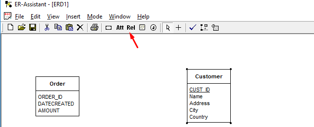


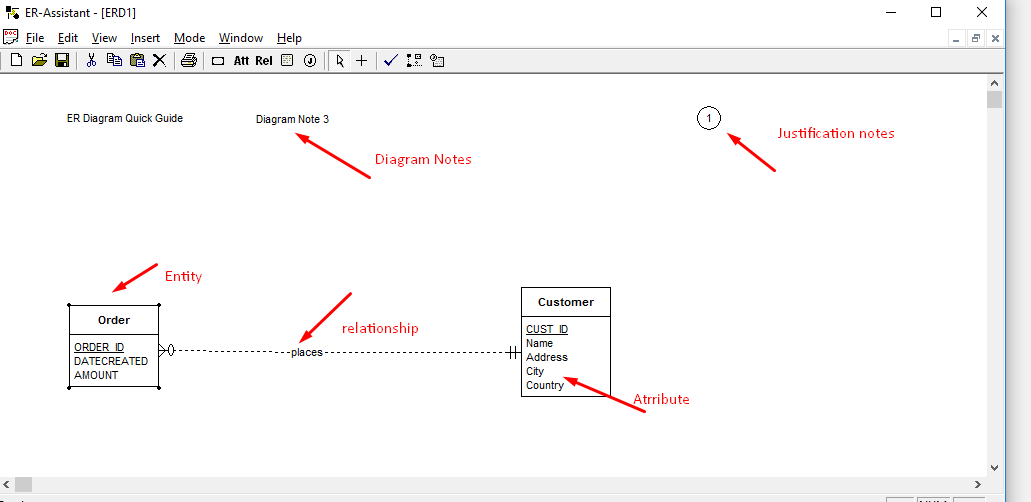
Good overview -thanks. Is there a way to widen these entity boxes forlonger attribute / entitiy names?
Hi Sudip,
Glad you like the overview.
Unfortunately, I have not found a way to resize the entity boxes yet. If you do find a way, do let me know. Good luck.
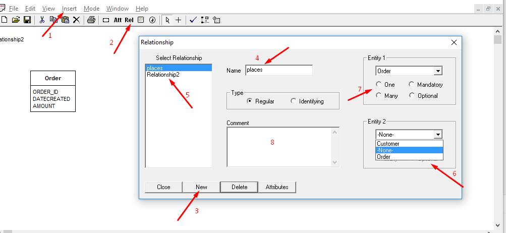
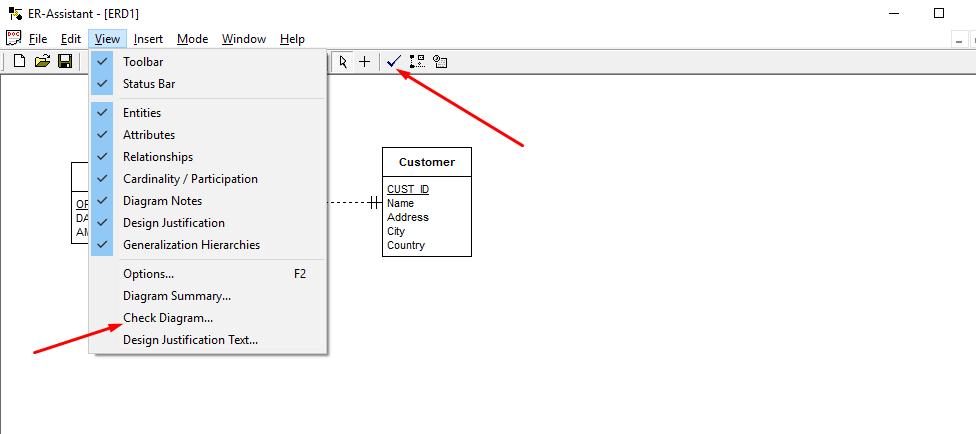
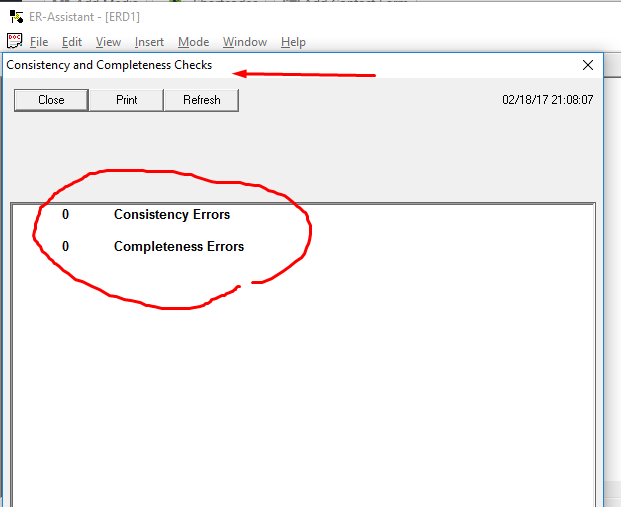
hi sudip . I did the relationships. When i check on the tick for errors it tells me there is incomplete cardanilty specification. What does that mean?
Hi Priya,
Your diagram is missing the cardinalities, so you will have to check and define all of them.
See what is being missed.
http://datapandas.com/wp-content/uploads/2017/03/cardinality.png
How can I resize the entity?
Hi Arnel ,
Unfortunately, I have not found a way to resize the entity boxes yet. If you do find a way, please do let me know. Thanks.
how do I create a self-referencing relationship for an entity?